

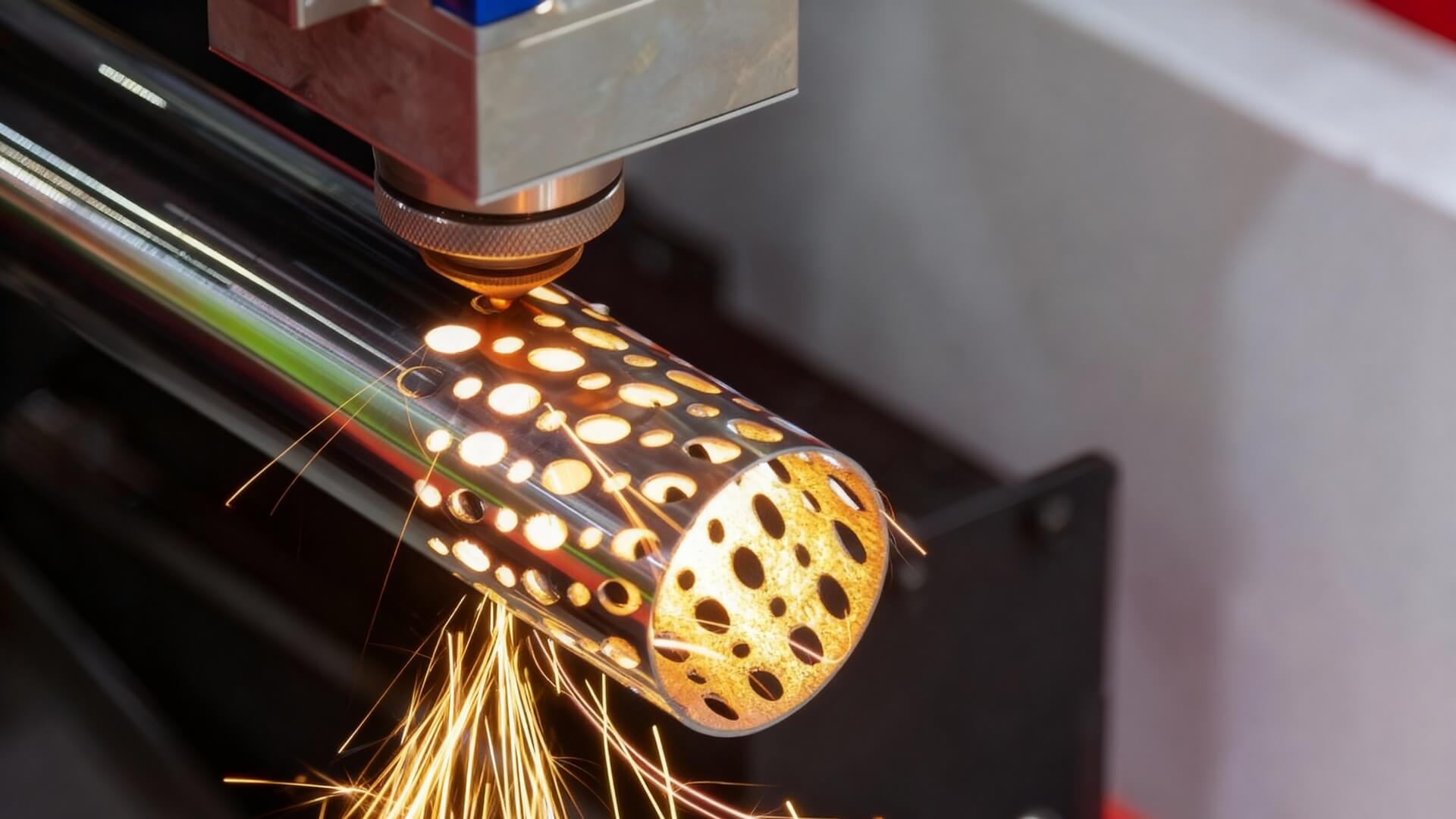
Tube laser cutting is used to produce cut features in tubes and profiles. Manufacturer systems are offered with different section ranges, handling arrangements and cutting modes, so selecting a machine requires more than a laser-power comparison. Define the incoming stock, finished geometry and complete production task before comparing proposals.
Specify the incoming tube or profile
Identify the material and grade, then describe the section. For round tube, record outside diameter and wall thickness. For rectangular or square tube, record both outside dimensions, wall thickness and the corner details stated on the stock drawing. For an open or special profile, attach its cross-section drawing.
Provide stock length, weight per length or per piece, and the supplier specification for the incoming material. State whether the tube is welded or seamless and identify any required orientation of a seam or surface. Mark variations and unknowns so the proposed handling and inspection approach can be reviewed.
Define the features and their reference points
Send the finished-part drawing with a revision number and the agreed digital model or file format. Identify cut-to-length ends, holes, slots, notches, miters and any bevel requirement. Keep the drawing requirements separate from assumptions about which machine can produce them.
State which face, end or axis is the dimensional reference. If holes on different faces must align, show their relationship on the drawing. For an assembly, include the mating part or assembly view so the supplier can discuss both dimensional inspection and a fit check.
Ask whether the proposed system supports the required cutting mode and approach angles. BLM GROUP’s range distinguishes tube-system configurations and cutting modes; that is a reason to check the exact proposal, not to infer that every tube machine offers the same features.
| Project area | What to send | What to confirm |
|---|---|---|
| Stock section | Material grade, cross-section, wall, corner details and stock tolerances. | Approved section range for the proposed configuration. |
| Handling | Stock and finished lengths, piece weight, batch size and floor layout. | Loading, support, unloading and handling of short finished parts. |
| Cut geometry | Revised drawing, digital model, holes, end cuts and bevel details. | Process route for each critical feature and any additional operation. |
| Material use | Required nesting mix and constraints on usable stock ends. | How the proposed setup accounts for clamping areas and remaining stock. |
| Acceptance | Datums, dimensional tolerances, internal condition and assembly checks. | Inspection method, representative samples and agreed pass criteria. |
Review the complete handling cycle
Ask the supplier to describe how the stock is located, held and supported throughout the job. Include the longest stock and the shortest finished part in the discussion. Confirm how finished pieces and remaining stock are removed and which steps require an operator.
Request the layout and utility requirements for the proposed system, including loading access and safe material movement. Where several sections or part families are planned, ask how tooling and program changes are handled. State the expected batch mix rather than comparing only a single long production run.
Agree sample and assembly acceptance
Choose sample parts that include the critical features on your real drawing. Record the incoming stock, machine configuration and drawing revision. Inspect dimensions from the agreed datums and document the condition of cut ends and features.
If the part specification limits internal residue, burrs or damage to an opposite surface, include an inspection method for those areas. For a frame or joint, add an assembly trial with the intended mating parts. A correct single hole does not establish that the complete assembly fits.
Compare cycle time for accepted parts, including loading, cutting, unloading, inspection and any finishing. Request the assumptions behind material-use and production figures. Keep the accepted sample record with the final equipment scope.
Tube cutting inquiry
- Stock: [material / grade / section / wall / length / piece weight]
- Variation: [stock tolerances, seam orientation and surface requirements]
- Part: [drawing revision, model, critical cuts and datum scheme]
- Handling: [loading method, finished length and floor-space constraints]
- Workload: [part mix and batch quantities]
- Acceptance: [dimensional, internal-surface and assembly checks]
Frequently asked questions
Can a sheet-cutting machine be assumed to handle tube? Ask for the exact tube-handling and cutting configuration. The machine name or laser power alone is insufficient.
How should I specify a rectangular tube? Send both outside dimensions, wall thickness and the section drawing, including the specified corners and stock variation.
Do I need an assembly drawing? Include it when the cut tube must locate or join with another part. It helps define the functional acceptance check.
Related reading and inquiries
Technical reference: BLM GROUP: tube laser cutting system configurations. This reference explains a process; its equipment specifications are not FINNLASER product specifications.
Send a tube-cutting inquiry. Include the information above so the proposed scope can be reviewed for your application.
FINNLASER accepts inquiries. This website does not offer online payment or shipping; any order terms must be confirmed separately.